Making Holdfasts
Over the years I’ve refined my process for making standard style woodworking holdfasts. A very similar process is used to make smaller diameter holdfasts for use with anvil pritchel holes. Type two holdfasts having an upset corner are made using a very different process.
Part 1, Holdfast Foot
I start with a 19.5 inch long, 3/4 inch diameter, A36 mild steel round bar. I smooth the ends and round the edges using a stationary belt sander.
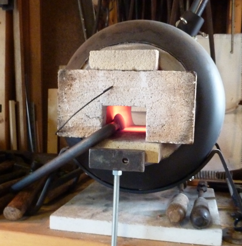
The end of the bar goes into the coke in the coal forge. I can form the holdfast foot in my gas forge but I prefer to use the coal forge when working with thicker materials due to faster heating.
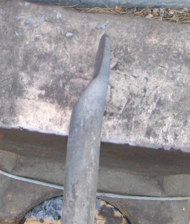
Once heated, I form a step in the end of the bar over a relatively sharp edge of the anvil.
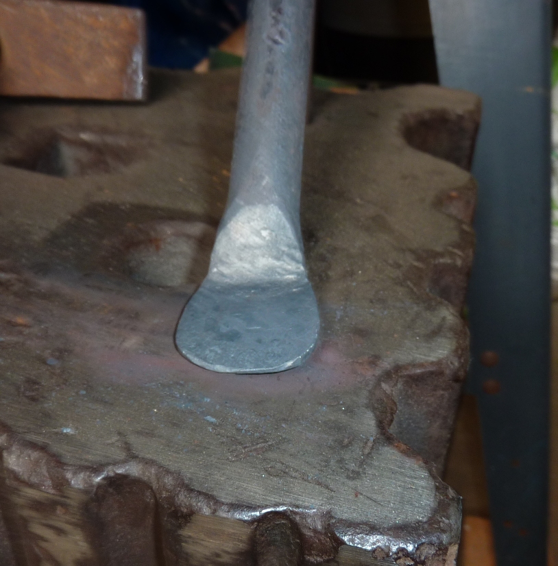
Here is the bottom view of the step in the bar.
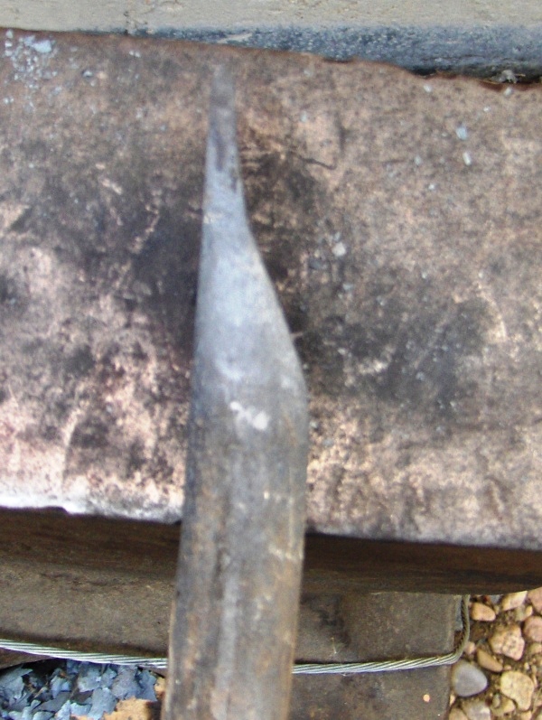
Next, I begin to draw out the underside of the step with the goal of moving material outward, to the left and to the right from the end of the bar using the hammer’s cross-peen. I then use the flat head of the hammer to further thin and smooth out the step.
Here is a view of the foot as it begins to take shape.
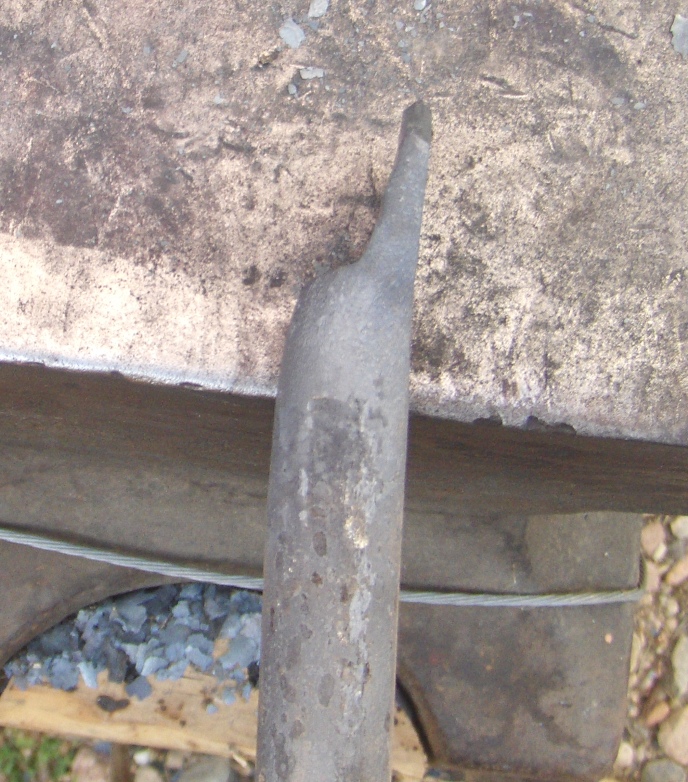
And another view of the foot.
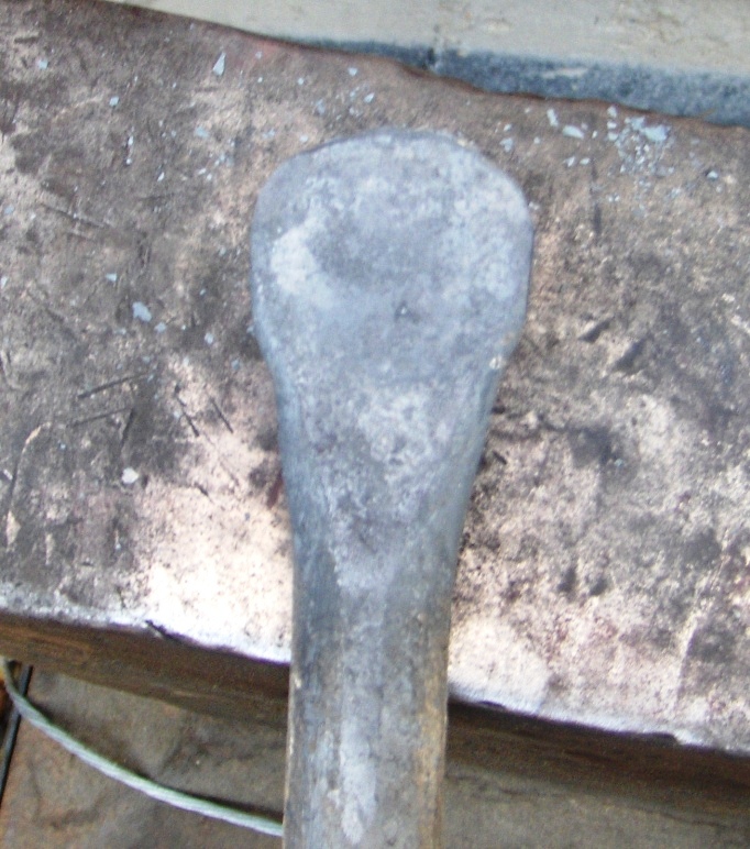
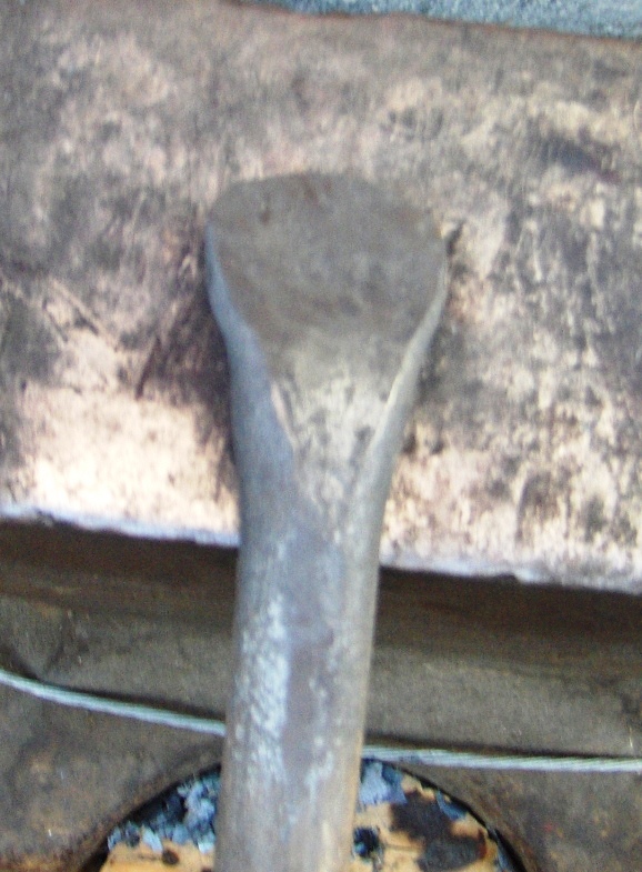
Next, I flatten the corner of the step that formed over the anvil’s edge.
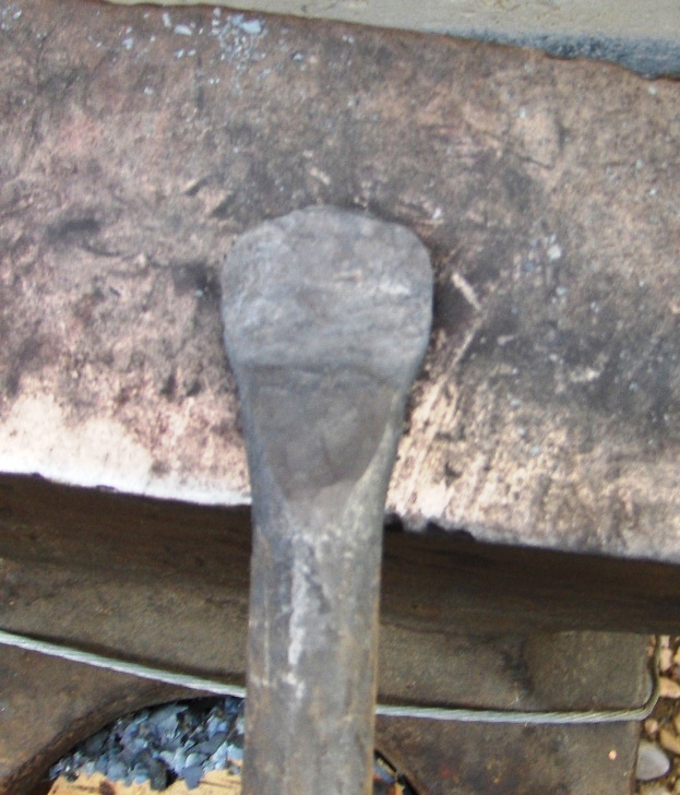
Another view.
Here is a side view showing the shape of the foot that I’m looking for.
Now flipping the bar over I am ready to begin bending the foot downwards. This is the surface that will do the clamping when the holdfast is completed.
The foot is beginning to bend downwards.
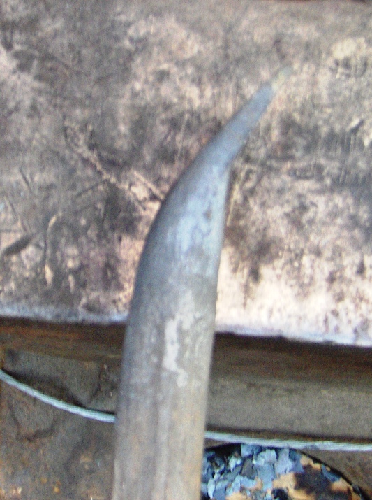
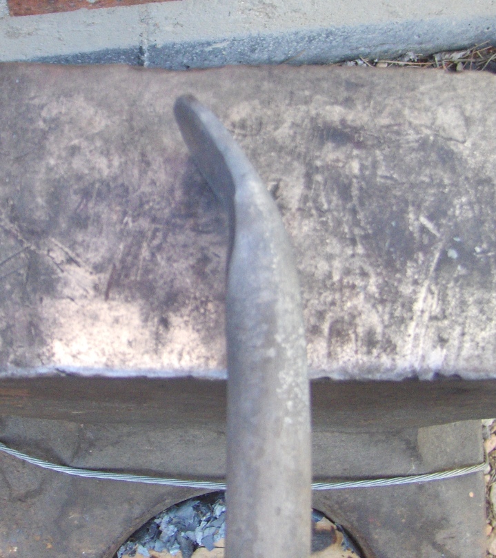
This is a side view of the foot after it’s bent.
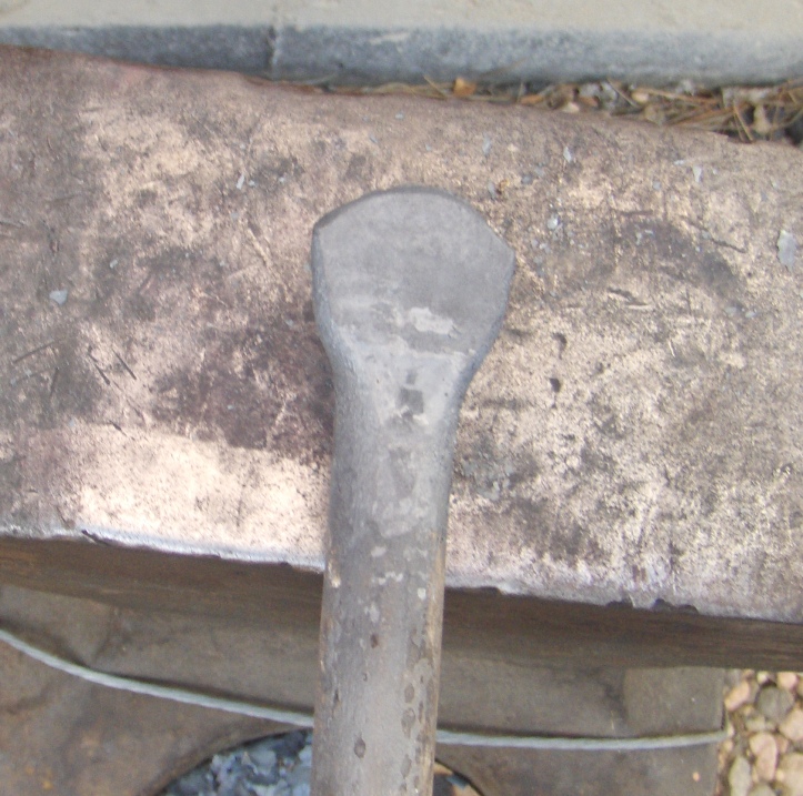
Another view of the nearly completed holdfast foot.
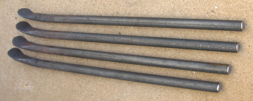
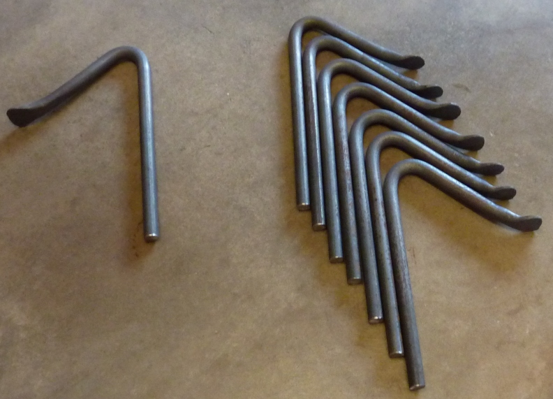
I generally make a number of holdfasts at a time and aim for shape consistency.
Part 2, Holdfast Arm Bend
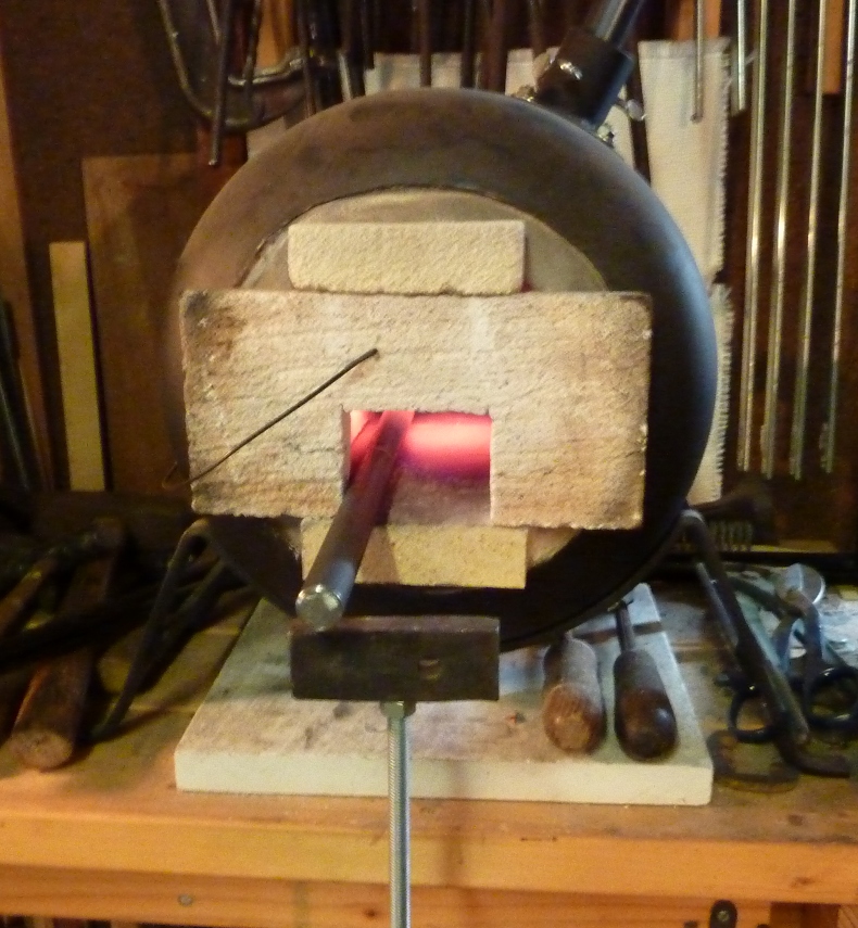
I like to heat the bar for the arm bend in my gas forge which allows me to better control the location and length of the heated zone. I generally try to minimize the heated zone length in order to obtain a relatively small bend radius.
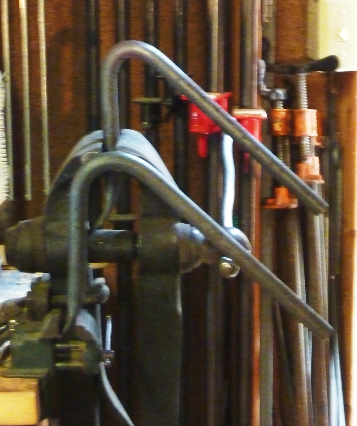
I bend the holdfast arm with the foot end clamped in my leg vise. Care must be taken to ensure that the bend is properly aligned with the foot. A completed holdfast is used as a bend reference.
I generally bend a number of holdfasts in a run and strive for consistency. Controlling the length and location of the heated zone is key.
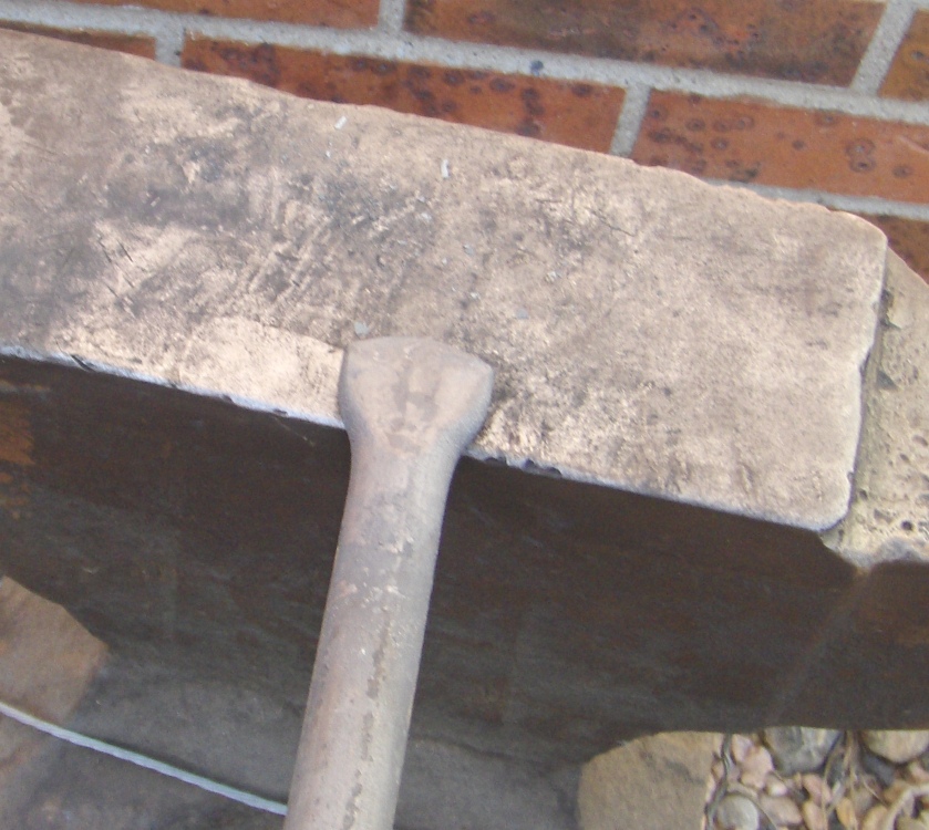
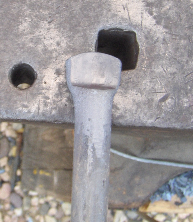
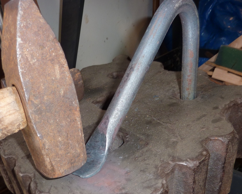
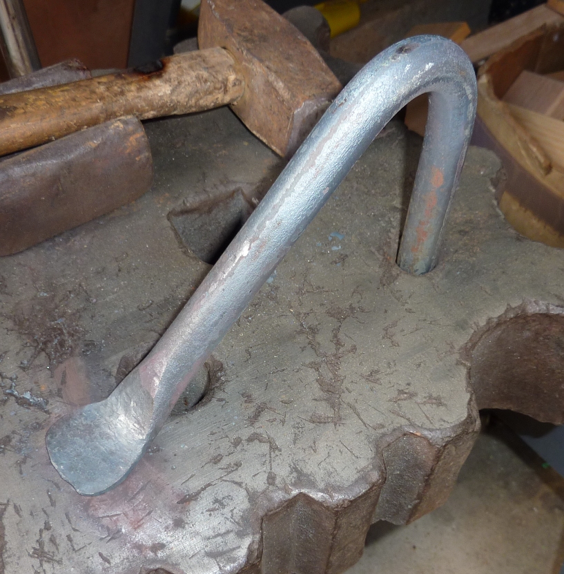
A foot alignment check is made with the holdfast inserted into a 3/4 inch hole in a thick swage block. There is some gaping on the right between the foot and the block’s top surface.
Here the foot is being heated so that its alignment can be fine adjusted.
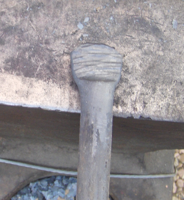
Final foot adjustments are made while the holdfast is inserted in the swage block.
Good contact is now made between the holdfast’s foot and the swage block surface.
Lastly, but not shown, final shaping of the edges of the foot and smoothing of the bottom of the foot is performed with the stationary belt sander. Then the holdfast receives final surface cleanup and is tested for clamping in 3/4″ holes in a workbench and the swage block.


